
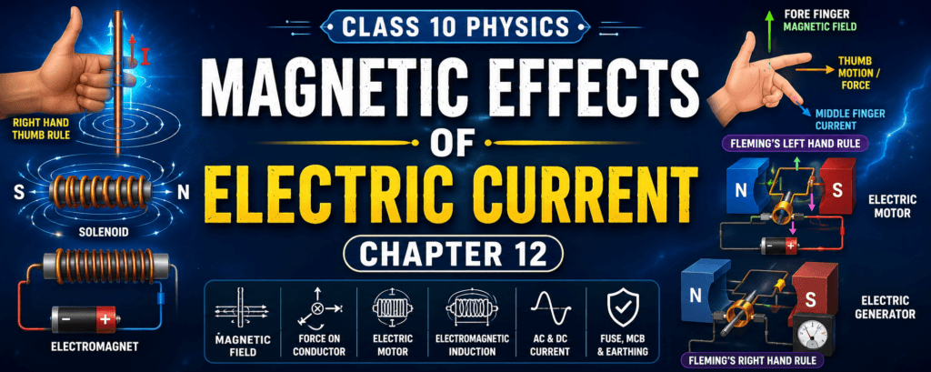
Introduction (Magnetic Effects of Electric Current Class 10 Notes)
Magnetism is one of the most fascinating phenomena in science. Have you ever wondered why a compass needle always points towards the north or how an electric motor in a fan works? The answer lies in the magnetic effect of electric current. This chapter explains how electricity and magnetism are interconnected and how this relationship has led to the invention of many devices used in our daily lives.
In the previous chapter, you learned about electric current, voltage, resistance, and electrical power. In this chapter, you will discover that whenever an electric current flows through a conductor, it produces a magnetic field around it. This principle forms the basis of devices such as electric motors, generators, transformers, loudspeakers, cranes, and many household appliances.
Understanding this chapter is important because questions related to magnetic fields, Fleming’s rules, electric motors, generators, and domestic electric circuits are frequently asked in the CBSE Class 10 board examination. (Magnetic Effects of Electric Current Class 10 Notes)
Learning Objectives
After studying this chapter, you will be able to:
- Explain the relationship between electricity and magnetism.
- Define magnetic field and magnetic field lines.
- Describe the magnetic field around a current-carrying conductor.
- Apply the Right-Hand Thumb Rule.
- Explain the magnetic field around a circular loop and a solenoid.
- Understand the construction and working of an electromagnet.
- Describe the working of an electric motor.
- Explain electromagnetic induction.
- Apply Fleming’s Left-Hand Rule and Right-Hand Rule.
- Understand the working of an electric generator.
- Explain the importance of fuse, MCB, and earthing in domestic electric circuits.
What is Magnetism?
Magnetism is a physical phenomenon produced by magnets or moving electric charges that causes attractive or repulsive forces between objects.
A magnet has the ability to attract magnetic materials such as:
- Iron
- Nickel
- Cobalt
- Steel (an alloy containing iron)
Magnets are widely used in daily life, including:
- Refrigerator doors
- Electric bells
- Loudspeakers
- Electric motors
- Generators
- Magnetic cranes
- Compasses
Definition
Magnetism is the property by which certain materials attract iron and other magnetic substances due to the presence of a magnetic field.
Magnets
A magnet is a material that produces a magnetic field around itself and attracts magnetic substances.
There are two main types of magnets:
1. Natural Magnets
Natural magnets occur in nature.
Example:
- Lodestone (Magnetite)
These magnets were discovered many centuries ago and were used for navigation.
2. Artificial Magnets
Artificial magnets are manufactured by humans in different shapes and sizes.
Examples:
- Bar magnet
- Horseshoe magnet
- Ring magnet
- Cylindrical magnet
Artificial magnets are stronger and more useful than natural magnets.
Magnetic Poles
Every magnet has two poles.
- North Pole (N)
- South Pole (S)
These poles are located near the ends of a magnet.
Important Properties
Like Poles Repel
- North – North → Repulsion
- South – South → Repulsion
Unlike Poles Attract
- North – South → Attraction
This property is used in electric motors, magnetic locks, and many industrial applications.
Exam Tip:
A magnet always has two poles. Even if it is cut into two pieces, each piece forms a new magnet with its own north and south poles.
Magnetic Materials
Magnetic materials are substances that can be attracted by a magnet.
Magnetic Materials
- Iron
- Nickel
- Cobalt
- Steel
These materials can be magnetized and are used to make electromagnets and electrical devices.
Non-Magnetic Materials
- Wood
- Plastic
- Glass
- Rubber
- Paper
- Copper
- Aluminium (very weakly magnetic under normal conditions)
These materials are generally not attracted by ordinary magnets.
Magnetic Field
A magnet does not need to touch an object to attract it. The region around the magnet where its magnetic force can be experienced is called the magnetic field.
Definition
A magnetic field is the region surrounding a magnet or a current-carrying conductor in which another magnet or magnetic material experiences a force.
Simply put,
A magnetic field is the invisible area around a magnet where magnetic forces act.
Characteristics of a Magnetic Field
- It surrounds every magnet.
- It is invisible.
- It exerts force on magnetic materials.
- Its strength is maximum near the poles.
- It decreases as the distance from the magnet increases.
Sources of Magnetic Field
A magnetic field can be produced by:
1. Permanent Magnet
A bar magnet continuously produces a magnetic field without requiring electricity.
Examples:
- Refrigerator magnet
- Compass needle
2. Current-Carrying Conductor
When electric current flows through a wire, it produces a magnetic field around the wire.
This important discovery was made by the Danish scientist Hans Christian Ørsted in 1820.
This discovery established the relationship between electricity and magnetism and laid the foundation for electromagnetism.
Magnetic Field Around Earth
The Earth behaves like a giant magnet.
This is why a compass needle always points approximately in the north–south direction.
The Earth’s magnetic field helps in:
- Navigation
- Direction finding
- Migration of birds and animals
- Protection from charged particles emitted by the Sun
Why is This Chapter Important?
This chapter explains the scientific principles behind many devices used in daily life, such as:
- Electric fans
- Mixers
- Washing machines
- Loudspeakers
- Electric bells
- Doorbells
- Magnetic cranes
- Electric generators
- Power stations
- Transformers
Understanding the magnetic effects of electric current helps students connect classroom concepts with real-world technology.
Key Terms
| Term | Meaning |
|---|---|
| Magnet | A material that produces a magnetic field and attracts magnetic substances. |
| Magnetism | The property of attraction or repulsion due to magnetic forces. |
| Magnetic Pole | The north or south end of a magnet where magnetic force is strongest. |
| Magnetic Material | A material that is attracted by a magnet, such as iron, nickel, or cobalt. |
| Magnetic Field | The region around a magnet or current-carrying conductor where magnetic force can be experienced. |
| Permanent Magnet | A magnet that retains its magnetic properties without external power. |
Quick Revision
- Magnetism is the force associated with magnets and moving electric charges.
- Every magnet has a north pole and a south pole.
- Like poles repel; unlike poles attract.
- A magnetic field is the region where magnetic force acts.
- Magnetic field strength is greatest near the poles.
- A current-carrying conductor also produces a magnetic field.
- Ørsted discovered the magnetic effect of electric current in 1820.
- The Earth itself behaves like a giant magnet.
Magnetic Field Lines
Magnetic field lines are imaginary lines used to represent the direction and strength of a magnetic field.
If a small compass is placed near a magnet, its north pole points in the direction of the magnetic field. By placing several compass needles around the magnet, we can trace the magnetic field lines.
Definition
Magnetic field lines are imaginary curves that represent the direction of the magnetic field around a magnet or a current-carrying conductor.
Characteristics of Magnetic Field Lines
Magnetic field lines have several important properties.
1. They Originate from the North Pole
Outside a magnet, magnetic field lines emerge from the North Pole and enter the South Pole.
Inside the magnet, they travel from the South Pole back to the North Pole, forming closed continuous loops.
Exam Point: Magnetic field lines never begin or end abruptly.
2. They Never Intersect
Two magnetic field lines can never cross each other.
If they crossed, the magnetic field would have two different directions at the same point, which is impossible.
3. They Form Closed Curves
Unlike electric field lines, magnetic field lines always form complete loops.
This is because magnetic poles always exist in pairs.
4. Closer Lines Indicate a Stronger Magnetic Field
When magnetic field lines are very close together, the magnetic field is stronger.
Near the poles of a magnet, the lines are crowded together because the magnetic force is maximum there.
Far away from the poles, the lines spread out, indicating a weaker magnetic field.
Activity: Observing Magnetic Field Lines
You can easily observe magnetic field lines using simple materials.
Materials Required
- Bar magnet
- White sheet of paper
- Iron filings
Procedure
- Place the bar magnet on a table.
- Cover it with a white sheet of paper.
- Sprinkle iron filings evenly over the paper.
- Gently tap the paper.
Observation
The iron filings arrange themselves in a definite pattern around the magnet.
This pattern represents the magnetic field lines.
Conclusion
Iron filings align along magnetic field lines, showing the shape and direction of the magnetic field.
Magnetic Field Around a Straight Current-Carrying Conductor
One of the most important discoveries in electromagnetism was made by Hans Christian Ørsted in 1820.
He observed that when electric current flows through a straight wire, a nearby compass needle gets deflected.
This proved that:
Electric current produces a magnetic field.
Experiment Demonstrating the Magnetic Effect of Current
Apparatus
- Straight copper wire
- Battery
- Switch
- Compass needle
Procedure
- Place the compass below the straight wire.
- Connect the wire to a battery through a switch.
- Close the switch to allow current to flow.
Observation
The compass needle deflects immediately.
When the direction of current is reversed, the compass needle deflects in the opposite direction.
Conclusion
A current-carrying conductor produces a magnetic field whose direction depends on the direction of current.
Shape of the Magnetic Field Around a Straight Wire
The magnetic field around a straight current-carrying conductor consists of concentric circular field lines.
These circles are centered on the wire.
The direction of these circles changes when the direction of current changes.
Factors Affecting the Strength of the Magnetic Field
The strength of the magnetic field around a conductor depends on the following factors.
1. Magnitude of Current
A larger electric current produces a stronger magnetic field.
- Small current → Weak magnetic field
- Large current → Strong magnetic field
2. Distance from the Wire
The magnetic field becomes weaker as the distance from the wire increases.
Near the wire, the field is strong.
Far away from the wire, the field is weak.
3. Nature of the Medium
The magnetic field can also vary depending on the surrounding material, although for Class 10, the focus is mainly on current and distance.
Right-Hand Thumb Rule
The Right-Hand Thumb Rule helps determine the direction of the magnetic field around a straight current-carrying conductor.
Definition
If you hold a straight conductor in your right hand such that:
- The thumb points in the direction of electric current,
- Then the curled fingers show the direction of the magnetic field lines.
This rule was proposed by James Clerk Maxwell.
How to Apply the Right-Hand Thumb Rule
Step 1
Hold the conductor with your right hand.
Step 2
Point your thumb in the direction of conventional current.
Step 3
Observe the direction in which your fingers curl.
That curling direction gives the direction of the magnetic field around the conductor.
Example
Suppose current flows upward through a vertical wire.
- Thumb → Upward
- Fingers curl around the wire
The curled fingers indicate the circular direction of the magnetic field.
If the current flows downward, the magnetic field direction also reverses.
Importance of the Right-Hand Thumb Rule
The Right-Hand Thumb Rule is useful for:
- Determining magnetic field direction.
- Understanding electromagnets.
- Explaining electric motors.
- Studying generators.
- Solving CBSE numerical and diagram-based questions.
Applications of Magnetic Field Around a Conductor
The magnetic effect of electric current is used in many devices.
Examples include:
- Electromagnets
- Electric bells
- Relays
- Loudspeakers
- Electric motors
- Generators
- Transformers
- MRI machines
- Magnetic cranes
Difference Between Magnetic Field of a Bar Magnet and a Current-Carrying Conductor
| Bar Magnet | Current-Carrying Conductor |
|---|---|
| Produced by a permanent magnet | Produced only when current flows |
| Field lines emerge from the North Pole and enter the South Pole | Field lines are concentric circles around the conductor |
| Exists continuously | Exists only while current is flowing |
| Strength depends on the magnet | Strength depends on the amount of current and distance |
Exam Tips
- Remember that magnetic field lines never intersect.
- Outside a magnet, field lines move from North to South.
- Around a straight conductor, the field lines are concentric circles.
- Use the Right-Hand Thumb Rule to determine the direction of the magnetic field.
- Reversing the current reverses the direction of the magnetic field.
Quick Revision
- Magnetic field lines are imaginary lines representing a magnetic field.
- They always form closed loops.
- They never intersect.
- Closer field lines indicate a stronger magnetic field.
- A straight current-carrying conductor produces concentric circular magnetic field lines.
- Increasing current increases the strength of the magnetic field.
- Increasing the distance from the conductor decreases the magnetic field strength.
- The Right-Hand Thumb Rule is used to determine the direction of the magnetic field around a straight current-carrying conductor.
Magnetic Field Around a Circular Current-Carrying Loop
When a straight conducting wire is bent into a circular loop and electric current passes through it, a magnetic field is produced around the loop.
Unlike a straight conductor, the magnetic field at the centre of the loop becomes much stronger because the magnetic fields produced by different parts of the loop combine together.
Definition
A circular current-carrying loop is a conducting wire bent into the shape of a circle through which electric current flows.
Formation of Magnetic Field
Each small part of the circular wire produces its own magnetic field.
At the centre of the loop, these magnetic fields act in the same direction and combine to produce a strong magnetic field.
This is why the centre of the loop has the maximum magnetic field strength.
Factors Affecting the Magnetic Field
The strength of the magnetic field depends on:
1. Amount of Current
Greater current produces a stronger magnetic field.
- High current → Strong field
- Low current → Weak field
2. Number of Turns
Increasing the number of turns increases the magnetic field.
More turns mean more individual magnetic fields combine together.
3. Radius of the Loop
A smaller loop produces a stronger magnetic field at its centre than a larger loop carrying the same current.
Direction of Magnetic Field
The direction of the magnetic field around a circular loop can also be determined using the Right-Hand Thumb Rule.
If the fingers of the right hand curl in the direction of current flowing through the loop, the thumb points in the direction of the magnetic field through the centre of the loop.
Applications of Circular Loops
Circular current-carrying loops are used in:
- Electric motors
- Loudspeakers
- Electromagnets
- Galvanometers
- Measuring instruments
Solenoid
A solenoid is one of the most important applications of the magnetic effect of electric current.
It produces a strong and nearly uniform magnetic field.
Definition
A solenoid is a long cylindrical coil made by winding many circular turns of insulated copper wire closely together.
When electric current flows through the solenoid, it behaves like a bar magnet.
Magnetic Field Around a Solenoid
When current passes through a solenoid:
- Each circular turn produces its own magnetic field.
- These fields combine to form one strong magnetic field.
- Inside the solenoid, the magnetic field is almost uniform.
- Outside the solenoid, the field resembles that of a bar magnet.
Properties of the Magnetic Field Inside a Solenoid
The magnetic field inside a solenoid has the following characteristics:
- Very strong
- Uniform
- Parallel magnetic field lines
- Nearly constant throughout the central region
Because of these properties, solenoids are widely used in electrical and electronic devices.
Why Does a Solenoid Behave Like a Bar Magnet?
A current-carrying solenoid has:
- One end behaving as the North Pole
- The opposite end behaving as the South Pole
Therefore, it attracts and repels magnets just like a bar magnet.
Factors Affecting the Strength of a Solenoid
1. Number of Turns
More turns produce a stronger magnetic field.
2. Magnitude of Current
Higher current increases the magnetic field strength.
3. Core Material
Placing a soft iron core inside the solenoid greatly increases the magnetic field.
This arrangement forms an electromagnet.
Electromagnet
An electromagnet is a temporary magnet produced by passing electric current through a solenoid wound around a soft iron core.
Unlike a permanent magnet, an electromagnet loses its magnetism when the current is switched off.
Definition
An electromagnet is a temporary magnet made by winding insulated wire around a soft iron core and passing electric current through it.
Construction of an Electromagnet
An electromagnet consists of:
- Soft iron core
- Insulated copper wire
- Battery or DC power supply
- Switch
When the switch is closed, electric current flows through the coil and magnetizes the soft iron core.
Working of an Electromagnet
- Electric current flows through the coil.
- The solenoid produces a magnetic field.
- The soft iron core becomes magnetized.
- A strong electromagnet is formed.
- When the current is switched off, the iron core loses most of its magnetism.
Advantages of Electromagnets
- Strong magnetic field
- Strength can be adjusted
- Can be switched ON and OFF
- Polarity can be reversed by reversing the current
- Suitable for industrial applications
Permanent Magnet vs Electromagnet
| Permanent Magnet | Electromagnet |
|---|---|
| Always magnetic | Magnetic only when current flows |
| Fixed strength | Strength can be varied |
| Cannot be switched off | Can be switched on and off |
| Usually made of hard steel | Usually made using soft iron |
| Polarity remains fixed | Polarity changes when current direction changes |
Applications of Electromagnets
Electromagnets are used in:
- Electric bells
- Relays
- Loudspeakers
- Electric motors
- Magnetic cranes
- MRI machines
- Circuit breakers
- Scrap lifting machines
- Door locks
- Industrial automation
Activity: Making a Simple Electromagnet
Materials Required
- Soft iron nail
- Insulated copper wire
- Battery
- Switch
- Paper clips
Procedure
- Wind the insulated copper wire around the iron nail.
- Connect both ends of the wire to a battery through a switch.
- Close the switch.
- Bring the nail near paper clips.
Observation
The nail attracts the paper clips.
When the switch is opened, the paper clips fall.
Conclusion
Electric current converts the iron nail into a temporary magnet.
Everyday Examples
Electromagnets are present in many household and industrial devices:
- Doorbells
- Washing machines
- Fans
- Mixers
- Loudspeakers
- Cranes used in scrapyards
- Automatic doors
Key Differences Between Circular Loop and Solenoid
| Circular Loop | Solenoid |
|---|---|
| Single circular turn or a few turns | Many closely wound circular turns |
| Produces a magnetic field around the loop | Produces a strong, nearly uniform magnetic field inside |
| Magnetic field is strongest at the centre | Magnetic field is strong throughout the interior |
| Used in simple circuits and instruments | Used to make electromagnets and electrical devices |
Exam Tips
- A solenoid behaves like a bar magnet.
- The magnetic field inside a solenoid is strong and nearly uniform.
- A soft iron core increases the strength of a solenoid.
- An electromagnet works only when electric current flows.
- Increasing the number of turns or the current increases the strength of the electromagnet.
Quick Revision
- A circular current-carrying loop produces a stronger magnetic field than a straight conductor.
- The magnetic field increases with current and the number of turns.
- A solenoid is a long coil of insulated wire.
- The magnetic field inside a solenoid is strong and uniform.
- A current-carrying solenoid behaves like a bar magnet.
- An electromagnet is made by placing a soft iron core inside a solenoid.
- Electromagnets are temporary magnets used in many electrical appliances and industries.
Force on a Current-Carrying Conductor
When a conductor carrying electric current is placed in a magnetic field, it experiences a force due to the interaction between the conductor’s magnetic field and the external magnetic field.
Definition
A current-carrying conductor placed in a magnetic field experiences a mechanical force that causes it to move.
This phenomenon is known as the motor effect.
Why Does the Conductor Move?
A current-carrying conductor produces its own magnetic field.
When this magnetic field interacts with the magnetic field of a permanent magnet:
- On one side, the magnetic fields reinforce each other.
- On the opposite side, they oppose each other.
This creates an unbalanced force, causing the conductor to move.
Activity: Observing Force on a Conductor
Materials Required
- Horseshoe magnet
- Straight copper wire
- Battery
- Switch
Procedure
- Suspend the wire between the poles of a horseshoe magnet.
- Connect the wire to a battery.
- Close the switch.
Observation
The wire moves sideways.
Reverse the direction of current.
The wire now moves in the opposite direction.
Conclusion
The direction of the force depends upon:
- Direction of current
- Direction of magnetic field
If either is reversed, the direction of motion also reverses.
Factors Affecting the Force
The force acting on a conductor depends on:
1. Strength of Magnetic Field
A stronger magnetic field produces a greater force.
2. Magnitude of Current
More current results in a larger force.
3. Length of Conductor Inside the Magnetic Field
A longer conductor within the magnetic field experiences a greater force.
Fleming’s Left-Hand Rule
To determine the direction of the force acting on a current-carrying conductor, we use Fleming’s Left-Hand Rule.
Definition
If the thumb, forefinger, and middle finger of the left hand are held mutually perpendicular to each other:
- Forefinger → Direction of magnetic field
- Middle Finger → Direction of current
- Thumb → Direction of force (motion)
This rule helps predict the direction in which the conductor will move.
How to Remember Fleming’s Left-Hand Rule
| Finger | Represents |
|---|---|
| Thumb | Force (Motion) |
| Forefinger | Magnetic Field |
| Middle Finger | Current |
A simple memory trick is:
F – B – I
- F → Force
- B → Magnetic Field
- I → Current
Importance of Fleming’s Left-Hand Rule
It is used in:
- Electric motors
- Loudspeakers
- Electric fans
- Washing machines
- Mixers
- Pumps
It is one of the most frequently asked concepts in the CBSE Class 10 board examination.
Electric Motor
An electric motor is one of the most important applications of the magnetic effect of electric current.
It converts electrical energy into mechanical energy.
Definition
An electric motor is a device that converts electrical energy into mechanical energy by using the force acting on a current-carrying conductor placed in a magnetic field.
Principle of an Electric Motor
An electric motor works on the principle that:
A current-carrying conductor placed in a magnetic field experiences a force.
The direction of this force is determined using Fleming’s Left-Hand Rule.
Construction of an Electric Motor
A simple DC electric motor consists of:
- Strong permanent magnets
- Rectangular coil (armature)
- Soft iron core
- Split-ring commutator
- Carbon brushes
- DC battery
Parts of an Electric Motor
1. Permanent Magnets
Provide a strong magnetic field.
2. Rectangular Coil (Armature)
Carries electric current.
Experiences magnetic force and rotates.
3. Soft Iron Core
Strengthens the magnetic field.
Improves motor efficiency.
4. Split-Ring Commutator
Its function is to reverse the direction of current in the coil after every half rotation.
This ensures continuous rotation in the same direction.
5. Carbon Brushes
Provide electrical contact between the battery and the rotating coil.
6. Battery
Supplies electric current to the motor.
Working of an Electric Motor
Step 1
When the switch is closed, electric current flows through the coil.
Step 2
The coil becomes a current-carrying conductor inside a magnetic field.
Step 3
Opposite sides of the coil experience forces in opposite directions.
One side moves upward.
The other side moves downward.
Step 4
These opposite forces rotate the coil.
Step 5
After half a rotation, the split-ring commutator reverses the direction of current.
Step 6
The direction of force also reverses.
The coil continues rotating in the same direction.
Step 7
This process repeats continuously, producing continuous rotational motion.
Energy Conversion in an Electric Motor
| Input | Output |
|---|---|
| Electrical Energy | Mechanical Energy |
Applications of Electric Motors
Electric motors are used in:
- Ceiling fans
- Water pumps
- Washing machines
- Mixers
- Grinders
- Vacuum cleaners
- Electric vehicles
- Lifts
- Cranes
- Drilling machines
- Industrial machinery
- Air conditioners
Advantages of Electric Motors
- High efficiency
- Reliable operation
- Easy maintenance
- Compact design
- Environment-friendly (when powered by clean electricity)
Difference Between Motor and Generator
| Electric Motor | Electric Generator |
|---|---|
| Converts electrical energy into mechanical energy | Converts mechanical energy into electrical energy |
| Uses Fleming’s Left-Hand Rule | Uses Fleming’s Right-Hand Rule |
| Consumes electricity | Produces electricity |
| Used in fans, pumps, mixers | Used in power stations and generators |
Exam Tips
- An electric motor converts electrical energy into mechanical energy.
- It works on the force acting on a current-carrying conductor placed in a magnetic field.
- Fleming’s Left-Hand Rule is used to determine the direction of motion.
- The split-ring commutator reverses the current after every half rotation.
- Carbon brushes maintain electrical contact with the rotating coil.
Key Terms
| Term | Meaning |
|---|---|
| Motor Effect | Force experienced by a current-carrying conductor placed in a magnetic field. |
| Fleming’s Left-Hand Rule | Rule used to determine the direction of force on a conductor. |
| Armature | Rotating current-carrying coil of the motor. |
| Split-Ring Commutator | Device that reverses current after every half rotation. |
| Carbon Brushes | Conduct electricity from the battery to the rotating coil. |
Quick Revision
- A current-carrying conductor placed in a magnetic field experiences a force.
- The direction of force depends on the direction of current and magnetic field.
- Fleming’s Left-Hand Rule predicts the direction of motion.
- An electric motor works on the motor effect.
- A split-ring commutator reverses the current every half turn to maintain continuous rotation.
- Electric motors convert electrical energy into mechanical energy and are used in many household and industrial appliances.
Electromagnetic Induction
One of the greatest discoveries in physics was made by the English scientist Michael Faraday in 1831.
He discovered that electric current can be produced without using a battery.
Instead, current is produced by changing the magnetic field around a conductor.
Definition
Electromagnetic induction is the phenomenon of producing electric current in a conductor by changing the magnetic field around it.
Faraday’s Experiment
Apparatus Required
- Coil of insulated copper wire
- Strong bar magnet
- Galvanometer
Procedure
- Connect the coil to a galvanometer.
- Move the magnet towards the coil.
Observation
The galvanometer shows a deflection.
Now move the magnet away from the coil.
The galvanometer deflects in the opposite direction.
Keep the magnet stationary.
The galvanometer shows no deflection.
Conclusion
Electric current is produced only when there is relative motion between the magnet and the coil.
A stationary magnet does not produce induced current.
Conditions for Electromagnetic Induction
Electric current is induced only when:
- A conductor moves in a magnetic field.
- A magnet moves towards or away from a conductor.
- The magnetic field around the conductor changes.
- There is relative motion between the conductor and the magnetic field.
Factors Affecting the Induced Current
The amount of induced current depends on:
1. Strength of Magnetic Field
A stronger magnetic field induces a larger current.
2. Speed of Motion
Moving the magnet faster produces a greater induced current.
3. Number of Turns in the Coil
More turns increase the induced current.
4. Area of the Coil
A larger coil intercepts more magnetic field lines and produces more induced current.
Fleming’s Right-Hand Rule
The direction of induced current is determined by Fleming’s Right-Hand Rule.
Definition
Stretch the thumb, forefinger, and middle finger of your right hand so that they are mutually perpendicular.
Then:
- Forefinger → Direction of magnetic field
- Thumb → Direction of motion of the conductor
- Middle Finger → Direction of induced current
Easy Trick to Remember
Right Hand = Generator
Thumb → Motion
Forefinger → Magnetic Field
Middle Finger → Current
Difference Between Fleming’s Left-Hand Rule and Right-Hand Rule
| Fleming’s Left-Hand Rule | Fleming’s Right-Hand Rule |
|---|---|
| Used for Electric Motor | Used for Electric Generator |
| Finds direction of Force | Finds direction of Induced Current |
| Converts Electrical Energy → Mechanical Energy | Converts Mechanical Energy → Electrical Energy |
Exam Tip:
Remember: Left = Motor, Right = Generator.
Electric Generator
An electric generator converts mechanical energy into electrical energy.
Generators are used in thermal power plants, hydroelectric stations, wind farms, and many other electricity-producing systems.
Definition
An electric generator is a device that converts mechanical energy into electrical energy using electromagnetic induction.
Principle of Electric Generator
An electric generator works on the principle of electromagnetic induction.
When a conductor rotates inside a magnetic field, an electric current is induced in the conductor.
Construction of an Electric Generator
A simple AC generator consists of:
- Strong permanent magnets
- Rectangular coil (armature)
- Slip rings
- Carbon brushes
- Shaft or turbine
Parts of an Electric Generator
1. Armature Coil
A rectangular coil of insulated copper wire that rotates in the magnetic field.
2. Permanent Magnets
Provide a strong magnetic field.
3. Slip Rings
Two slip rings are attached to the ends of the rotating coil.
They allow current to flow to the external circuit while the coil rotates continuously.
4. Carbon Brushes
Carbon brushes maintain electrical contact with the rotating slip rings.
5. Turbine or Shaft
Provides mechanical energy by rotating the coil.
The turbine may be driven by:
- Water
- Steam
- Wind
- Diesel engine
Working of an Electric Generator
Step 1
Mechanical energy rotates the armature coil between the poles of a magnet.
Step 2
As the coil rotates, it cuts the magnetic field lines.
Step 3
An electric current is induced in the coil due to electromagnetic induction.
Step 4
The direction of induced current changes after every half rotation.
Step 5
Current flows through the slip rings and carbon brushes to the external circuit.
Step 6
Continuous rotation produces continuous electrical energy.
Energy Conversion in a Generator
| Input | Output |
|---|---|
| Mechanical Energy | Electrical Energy |
Alternating Current (AC)
Alternating Current is the type of current used in our homes.
Definition
Alternating Current (AC) is the electric current that changes both its direction and magnitude periodically.
Characteristics
- Changes direction repeatedly.
- Frequency in India is 50 Hz.
- Easily transmitted over long distances.
- Used in homes, schools, industries, and offices.
Examples
- Household electricity
- Ceiling fans
- Refrigerators
- Air conditioners
- Washing machines
Direct Current (DC)
Direct Current flows in only one direction.
Definition
Direct Current (DC) is the electric current that flows continuously in one direction.
Characteristics
- Flows in one direction only.
- Produced by batteries and cells.
- Used in electronic devices.
Examples
- Torch
- Mobile phone battery
- Laptop battery
- Power bank
- Solar battery
Difference Between AC and DC
| Alternating Current (AC) | Direct Current (DC) |
|---|---|
| Changes direction periodically | Flows only in one direction |
| Frequency is 50 Hz in India | Frequency is 0 Hz |
| Produced by AC generators | Produced by batteries and cells |
| Used in homes and industries | Used in electronic devices and portable gadgets |
| Suitable for long-distance transmission | Less suitable for long-distance transmission |
Applications of Electric Generators
Electric generators are widely used in:
- Hydroelectric power plants
- Thermal power stations
- Nuclear power plants
- Wind turbines
- Diesel generators
- Emergency backup systems
- Portable generators
Everyday Examples of Electromagnetic Induction
- Bicycle dynamo
- Wind turbines
- Power station generators
- Mobile phone wireless chargers
- Induction cooktops
- Transformers (based on electromagnetic induction)
Exam Tips
- Electromagnetic induction was discovered by Michael Faraday.
- Electric current is induced only when the magnetic field changes.
- Fleming’s Right-Hand Rule gives the direction of induced current.
- A generator converts mechanical energy into electrical energy.
- Slip rings are used in AC generators.
- Alternating current changes direction periodically, whereas direct current flows in only one direction.
Key Terms
| Term | Meaning |
|---|---|
| Electromagnetic Induction | Production of electric current due to changing magnetic field. |
| Induced Current | Current produced in a conductor by electromagnetic induction. |
| Electric Generator | Device that converts mechanical energy into electrical energy. |
| Slip Rings | Rings that transfer current from a rotating coil to the external circuit in an AC generator. |
| Alternating Current (AC) | Current that changes direction periodically. |
| Direct Current (DC) | Current that flows only in one direction. |
Quick Revision
- Electromagnetic induction is the production of electric current due to a changing magnetic field.
- Michael Faraday discovered electromagnetic induction in 1831.
- Fleming’s Right-Hand Rule determines the direction of induced current.
- An electric generator converts mechanical energy into electrical energy.
- AC changes direction periodically and is supplied to homes.
- DC flows in one direction and is supplied by batteries.
Domestic Electric Circuit
A domestic electric circuit is the electrical wiring system used in homes to distribute electricity safely to various electrical appliances.
Electricity is supplied to houses from nearby power stations through transmission and distribution lines.
In India, the domestic power supply is generally:
- Voltage: 220 V – 240 V
- Frequency: 50 Hz
- Type of Current: Alternating Current (AC)
Main Components of a Domestic Electric Circuit
A typical domestic electric circuit consists of:
- Electric Pole
- Service Wire
- Energy Meter
- Main Fuse
- Main Switch
- Miniature Circuit Breaker (MCB)
- Live Wire
- Neutral Wire
- Earth Wire
- Electrical Appliances
Wires Used in Domestic Wiring
Three wires are commonly used in household wiring.
1. Live Wire (Phase Wire)
The live wire carries electric current from the power supply to the electrical appliance.
Characteristics
- Usually red or brown in colour.
- It is at high potential.
- It carries current to the appliance.
2. Neutral Wire
The neutral wire provides the return path for electric current.
Characteristics
- Usually black or blue in colour.
- It is at nearly zero potential.
- It completes the electric circuit.
3. Earth Wire
The earth wire is a safety wire.
It connects the metallic body of electrical appliances to the ground.
Characteristics
- Usually green or green-yellow.
- Prevents electric shock.
- Carries leakage current safely into the Earth.
Live Wire vs Neutral Wire vs Earth Wire
| Live Wire | Neutral Wire | Earth Wire |
|---|---|---|
| Carries current to appliance | Returns current to source | Carries leakage current to Earth |
| High potential | Zero potential | Zero potential |
| Red/Brown colour | Black/Blue colour | Green or Green-Yellow colour |
| Essential for operation | Completes the circuit | Provides safety |
Electric Fuse
A fuse is one of the simplest safety devices used in electrical circuits.
It protects appliances from excessive current.
Definition
A fuse is a safety device that melts automatically when excessive current flows through a circuit, thereby breaking the circuit.
Fuse Wire
Fuse wire is made of a special alloy having:
- Low melting point
- High resistance
Commonly used materials include alloys of tin and lead.
Working of a Fuse
Under normal conditions:
- Current flows safely.
- Fuse wire remains intact.
When excessive current flows:
- The fuse wire becomes hot.
- It melts.
- The circuit breaks.
- Current supply stops immediately.
This protects appliances from damage.
Causes of Excessive Current
There are two main reasons.
1. Overloading
Overloading occurs when many high-power appliances are connected to the same circuit simultaneously.
Examples
- Heater
- Air conditioner
- Electric iron
- Microwave oven
Running all these together on one circuit may draw excessive current.
2. Short Circuit
A short circuit occurs when the live wire comes into direct contact with the neutral wire due to damaged insulation or faulty wiring.
This creates a very low-resistance path.
As a result:
- Current increases suddenly.
- Heat is produced.
- Fire may occur.
Miniature Circuit Breaker (MCB)
Modern houses use MCBs instead of traditional fuse wires.
Definition
A Miniature Circuit Breaker (MCB) is an automatic electrical safety device that switches off the circuit whenever excessive current flows.
Working of an MCB
When excessive current flows:
- The MCB automatically trips.
- The electrical circuit opens.
- Current supply stops immediately.
Unlike a fuse, the MCB does not melt.
It can simply be reset after the fault is corrected.
Advantages of MCB Over Fuse
| Fuse | MCB |
|---|---|
| Melts during overload | Trips automatically |
| Needs replacement | Can be reset |
| Slower operation | Faster operation |
| Less convenient | More convenient |
| Mostly used in old houses | Widely used in modern homes |
Earthing
Earthing is one of the most important electrical safety measures.
Definition
Earthing is the process of connecting the metallic body of an electrical appliance to the Earth through a thick conducting wire.
Why is Earthing Necessary?
Sometimes due to insulation failure:
- The live wire touches the metallic body of an appliance.
- The appliance becomes electrically charged.
- Touching it may result in an electric shock.
Earthing prevents this danger.
Working of Earthing
When leakage current appears:
- It flows through the earth wire.
- The current safely enters the ground.
- The metallic body remains at nearly zero potential.
- The user is protected from electric shock.
Importance of Earthing
Earthing:
- Protects human life.
- Prevents electric shock.
- Protects electrical appliances.
- Reduces fire hazards.
- Provides a safe path for leakage current.
Electric Shock
An electric shock occurs when electric current passes through the human body.
The severity depends on:
- Magnitude of current.
- Duration of contact.
- Path of current through the body.
Safety Precautions While Using Electricity
Always follow these precautions:
- Never touch electrical appliances with wet hands.
- Switch off the main power before repairing electrical equipment.
- Use properly insulated wires.
- Do not overload electrical sockets.
- Replace damaged wires immediately.
- Ensure proper earthing of heavy appliances.
- Use MCBs instead of old fuse systems.
- Keep electrical appliances away from water.
- Never insert metallic objects into electric sockets.
- Use ISI-certified electrical appliances.
Household Appliances That Require Earthing
Earthing is especially important for appliances with metallic bodies, such as:
- Refrigerator
- Washing machine
- Electric iron
- Water heater (geyser)
- Microwave oven
- Air conditioner
- Water cooler
Difference Between Fuse and Earthing
| Fuse | Earthing |
|---|---|
| Protects the circuit | Protects the user |
| Breaks the circuit during overload | Carries leakage current safely to the ground |
| Connected in series | Connected to the appliance body |
| Prevents damage to appliances | Prevents electric shoc |
Difference Between Overloading and Short Circuit
| Overloading | Short Circuit |
|---|---|
| Too many appliances connected | Live wire touches neutral wire |
| Current increases gradually | Current increases suddenly |
| Causes overheating | Causes sparks and fire |
| Prevented by proper load distribution | Prevented by proper insulation and wiring |
CBSE Important Points
- Domestic electricity supplied in India is 220–240 V AC at 50 Hz.
- A fuse works due to the heating effect of electric current.
- MCB stands for Miniature Circuit Breaker.
- Earthing protects users from electric shock.
- Overloading and short circuits are the two main causes of excessive current.
- Modern homes generally use MCBs instead of traditional fuses.
Key Terms
| Term | Meaning |
|---|---|
| Domestic Electric Circuit | Wiring system used in homes to distribute electricity safely. |
| Live Wire | Wire that carries current to the appliance. |
| Neutral Wire | Wire that returns current to the source. |
| Earth Wire | Safety wire that carries leakage current to the Earth. |
| Fuse | Safety device that melts during excessive current. |
| MCB | Automatic device that trips during overload or short circuit. |
| Earthing | Connecting the appliance body to the Earth for safety. |
| Overloading | Excessive current due to many appliances connected together. |
| Short Circuit | Direct contact between live and neutral wires causing a sudden surge of current. |
Quick Revision
- Domestic supply in India is 220–240 V AC, 50 Hz.
- Live wire supplies current, neutral wire returns it, and earth wire provides safety.
- A fuse melts when excessive current flows.
- An MCB automatically trips and can be reset.
- Earthing protects users from electric shock.
- Overloading and short circuits are the major causes of excessive current.
- Always use properly insulated wiring and avoid overloading electrical circuits.
Important Formulae
Although this chapter is mostly concept-based, a few important relations should be remembered.
1. Magnetic Field Around a Long Straight Conductor
Where,
- B = Magnetic field strength
- I = Electric current
- r = Distance from the conductor
Conclusion
- Magnetic field increases with current.
- Magnetic field decreases with distance.
2. Factors Affecting Magnetic Field of a Solenoid
The magnetic field increases with:
- Number of turns (N)
- Electric current (I)
- Soft iron core
3. Electrical Energy Conversion
Electric Motor
Electrical Energy → Mechanical Energy
Electric Generator
Mechanical Energy → Electrical Energy
Important Scientists
| Scientist | Contribution |
|---|---|
| Hans Christian Ørsted | Discovered the magnetic effect of electric current (1820). |
| Michael Faraday | Discovered electromagnetic induction (1831). |
| John Ambrose Fleming | Proposed the Left-Hand Rule and Right-Hand Rule. |
Most Important Definitions
Magnetism
The property by which certain materials attract or repel each other due to magnetic forces.
Magnetic Field
The region around a magnet or current-carrying conductor where magnetic force can be experienced.
Solenoid
A long cylindrical coil made by winding insulated copper wire in many closely spaced turns.
Electromagnet
A temporary magnet produced when electric current flows through a solenoid wound around a soft iron core.
Electromagnetic Induction
The phenomenon of producing electric current in a conductor by changing the magnetic field around it.
Electric Motor
A device that converts electrical energy into mechanical energy.
Electric Generator
A device that converts mechanical energy into electrical energy.
Important Differences
Motor vs Generator
| Electric Motor | Electric Generator |
|---|---|
| Converts electrical energy into mechanical energy | Converts mechanical energy into electrical energy |
| Uses Fleming’s Left-Hand Rule | Uses Fleming’s Right-Hand Rule |
| Consumes electricity | Produces electricity |
| Uses split-ring commutator (DC motor) | Uses slip rings (AC generator) |
AC vs DC
| Alternating Current (AC) | Direct Current (DC) |
|---|---|
| Changes direction periodically | Flows only in one direction |
| Frequency = 50 Hz (India) | Frequency = 0 Hz |
| Used in homes | Used in batteries and electronic devices |
Fuse vs MCB
| Fuse | MCB |
|---|---|
| Melts during overload | Trips automatically |
| Needs replacement | Can be reset |
| Less convenient | More convenient and safer |
Permanent Magnet vs Electromagnet
| Permanent Magnet | Electromagnet |
|---|---|
| Always magnetic | Magnetic only when current flows |
| Fixed strength | Adjustable strength |
| Cannot be switched off | Can be switched on and off |
Complete Chapter Summary
- Magnetism is the force associated with magnets and moving electric charges.
- A current-carrying conductor produces a magnetic field around it.
- The magnetic field around a straight conductor consists of concentric circles.
- The Right-Hand Thumb Rule gives the direction of the magnetic field around a current-carrying conductor.
- A circular loop produces a stronger magnetic field than a straight conductor.
- A solenoid behaves like a bar magnet and produces a strong, nearly uniform magnetic field.
- Placing a soft iron core inside a solenoid forms an electromagnet.
- A current-carrying conductor placed in a magnetic field experiences a force (motor effect).
- Fleming’s Left-Hand Rule predicts the direction of force on a conductor.
- An electric motor converts electrical energy into mechanical energy.
- Electromagnetic induction is the production of electric current due to a changing magnetic field.
- Fleming’s Right-Hand Rule predicts the direction of induced current.
- An electric generator converts mechanical energy into electrical energy.
- Domestic electric circuits include live, neutral, and earth wires.
- Fuse, MCB, and earthing protect users and appliances from electrical hazards.
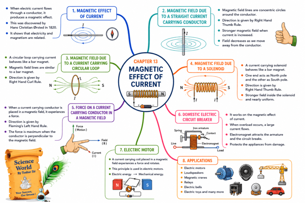
Text-Based Mind Map
15 Exam Tips
- Learn Ørsted, Faraday, and Fleming with their discoveries.
- Draw neat and labelled diagrams for magnetic field lines.
- Practise both Fleming’s Left-Hand Rule and Right-Hand Rule.
- Do not confuse motor with generator.
- Revise differences between AC and DC.
- Remember that a solenoid behaves like a bar magnet.
- Know the role of the split-ring commutator in a DC motor.
- Know the role of slip rings in an AC generator.
- Understand why earthing prevents electric shock.
- Revise the working of fuse and MCB.
- Draw circuit diagrams carefully.
- Use scientific terms in descriptive answers.
- Highlight keywords while revising.
- Practise NCERT in-text and exercise questions.
- Solve previous years’ CBSE questions for this chapter.
Frequently Asked Questions (FAQs)
1. What is the magnetic effect of electric current?
It is the phenomenon in which a current-carrying conductor produces a magnetic field around itself.
2. Who discovered the magnetic effect of electric current?
Hans Christian Ørsted discovered it in 1820.
3. What is a magnetic field?
A magnetic field is the region around a magnet or current-carrying conductor where magnetic force can be experienced.
4. What is the Right-Hand Thumb Rule?
It is a rule used to determine the direction of the magnetic field around a straight current-carrying conductor.
5. What is a solenoid?
A solenoid is a long cylindrical coil made of many closely wound turns of insulated wire that produces a strong magnetic field when current flows through it.
6. What is an electromagnet?
An electromagnet is a temporary magnet produced by passing electric current through a solenoid wound around a soft iron core.
7. What is electromagnetic induction?
It is the process of producing electric current in a conductor by changing the magnetic field around it.
8. What is the difference between an electric motor and an electric generator?
An electric motor converts electrical energy into mechanical energy, whereas an electric generator converts mechanical energy into electrical energy.
9. Why is earthing important?
Earthing provides a safe path for leakage current, preventing electric shocks and protecting electrical appliances.
10. Which topics are important for the CBSE Class 10 exam?
The most important topics include:
- Right-Hand Thumb Rule
- Fleming’s Left-Hand Rule
- Fleming’s Right-Hand Rule
- Electric Motor
- Electric Generator
- Solenoid
- Electromagnetic Induction
- Fuse, MCB, and Earthing
- Differences between AC and DC
- Magnetic field diagrams
Final Revision Checklist
Before your exam, make sure you can confidently explain:
- ✅ Magnetic field and magnetic field lines
- ✅ Right-Hand Thumb Rule
- ✅ Magnetic field around a straight conductor
- ✅ Circular loop and solenoid
- ✅ Electromagnet
- ✅ Force on a current-carrying conductor
- ✅ Fleming’s Left-Hand Rule
- ✅ Electric motor
- ✅ Electromagnetic induction
- ✅ Fleming’s Right-Hand Rule
- ✅ Electric generator
- ✅ AC and DC
- ✅ Domestic electric circuits
- ✅ Fuse, MCB, and earthing
- ✅ Important diagrams and definitions
📘 Prepare Smarter with the Complete CBSE Class 10 Science Master Guide
These free notes cover the essential concepts of Control and Coordination. For complete board exam preparation, explore the CBSE Class 10 Science Master Guide by Science World By Tushar Sir.
📖 What’s Inside the Book?
- ✅ Complete chapter-wise theory
- ✅ Easy-to-understand diagrams and flowcharts
- ✅ Mind Maps for quick revision
- ✅ Chapter-wise MCQs
- ✅ Assertion & Reason Questions
- ✅ Case-Based Questions
- ✅ Short & Long Answer Questions
- ✅ Practice Papers
- ✅ Smart Exam Strategies

📚 Available Formats
- 📕 Paperback Edition
- 📱 eBook Edition